Stuff4FS - Don's User Applications
AI Flight Planer (AIFP) V.3.4.3.15
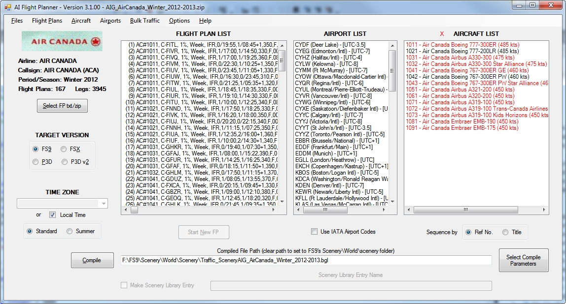
AI Flight Planner is a fully-integrated, TTools format-compatible AI flight planning tool for Microsoft Flight Simulator, both FS9 and FSX versions and Prepar3D. Introduced in May 2008 and continually upgraded since then, AI Flight Planner has become the tool of choice for preparing and editing AI flight plans. Many of its features including, in particular, the recently-developed universal repaint installer were developed in cooperation with AIG (Alpha-India Group). While intended to meet AIG's specific requirements, AI Flight Planner remains a general purpose tool that may be used to install anyone's flight plans and repaint packages.
AI Flight Planner Version 3 is, for the most part, a "facelift" for its predecessor. Gone are the separate opening screens for the flight plan/repaint installer and the flight plan editor. The flight plan editing controls have been moved to a separate dialog. A new, single Main Panel serves both the installer and editing functions. Most of the controls on the old installer panel remain on the new Main Panel. Functions related to those buttons that have been removed are now accessed via the main menu bar. All dialogs than can benefit from it, including the Main Panel, are now resizable. Location and size of most dialogs is now saved, both intra- and inter-session. So they will re-open as they were when last closed. You should also find more consistency in operation across all dialogs. For example, a double-click on any Flight Plan, Airport or Aircraft List item opens a suitable editor. Hovering the mouse over any such list item displays a tool tip including more information on the item. A right-click on any such item selects that item and presents a context menu of common operations for that item. The full compliment of operations is, of course, always available from the main menu bar. Nothing has been removed.
Version 3 also includes a few minor enhancements, particularly in the handling of bulk traffic files and its user manual has been extensively reorganized and revised, combining the two earlier manuals and also adding illustrations of most dialogs and lots of "how to" text.
Among AI Flight Planner's unique features are:
- arrival and departure times may be specified using local times
- use of either IATA or ICAO airport designators
- ICAO and IATA codes, UTC-offset and positional data for any airport is only a few mouse clicks away
- aircraft may be assigned directly from FS9 or FSX aircraft folders
- flight plans are created and edited on a per leg basis; using a day-of-week field, similar legs in weekly flight plans need be entered only once.
- the ability to extract from airline system-wide flight-plan data only those flight plans that visit any of a user-selected list of airports and to prepare subsets of flight plans based on aircraft used or destination airports
- an aircraft editor to manage all aircraft AI-related parameters and which will display a thumbnail of the selected aircraft if available
- stock and add-on airport data collection
- subsetting of flight plans by airport (both inclusive and exclusive)
- a "smart" tree-view display which differentiates between files/folders of interest and those that are not
- the ability to edit weekly flight plans for multiple days irrespective of whether or not in the consolidate mode
- a variety of traffic file "find" functions
- extensive traffic file and parking analysis capabilities
- TTools-format text files or compiled traffic files as source
- conversion of FS9 flight plans and traffic files for use with FSX
- creation and editing of flight plans in either the custom flight plan leg editor or a plain text editor
- user-specifiable standard "sit-times"
- built-in aircraft, airport and time-zone editors
- validation of all aspects of flight plans/li>
- compilation of flight plan data into flight simulator traffic files
Download this application...
Static Aircraft .mdl Maker (SAMM) V.2.2.10.0
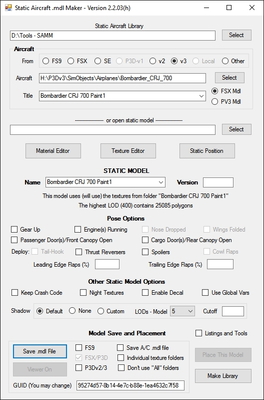
Tired of having to program AI (and suffer the overhead) just to have some "eye candy" sitting around your airport. No more! Static Aircraft .mdl Maker ("SAMM") will convert just about any Microsoft Flight Simulator or Lockheed Martin Prepar3D (Collectively "FlightSim") flyable or AI aircraft into a FS9, FSX oe P3D scenery model. Just "point" SAMM to the aircraft you wish to convert, decide where to save the scenery file and, presto, "eye candy".
Version 2 of SAMM
- creates static models of FS8, FS9, FSX and P3D aircraft (the latter two require the applicable SDK be installed)
- has an integrated model viewer
- converts static models of FlightSim version aircraft for use with any other version (requires access to the SDKs)
- supports a number of texture processing features utilizing Martin Wright's graphics processing .dlls if installed
- allows custom shadow generation to minimize FPS impact
- supports local libraries of aircraft
Creating a static model in three steps:
- specify the set of aircraft folders containing the model of interest
- click the Select button beside the Aircraft Folder textbox and navigate to the aircraft of interest
- if more than one version of that aircraft exists, select the desired aircraft title from the Title combobox
You can create models in a variety of poses
- gear up or down (if the gear retracts)
- engines running or off (FS8/9 aircraft only)
- doors open or closed
- flaps deployed or not
Once the model(s) are created, you can place them individually using the built-in placement function, or create a library of models for placement by one of the many available object placement utilities.
Unfortunately, not every aircraft model converts using the default settings. If one of yours doesn't and there's no alternative, SAMM includes a set of "Tools" for determining what is the problem and allows you to set individual aircraft parameter values to correct the situation. SAMM is compatible with P3D v5 to the extent it will convert aircraft resident in PV5 folders. However, no new conversion cababilities have been added to address new capabilities of PV5.
Download this application...
Airfield Lights Toolbox (AFLT) V.4.5.3.5
Airfield Lights Toolbox (or AFLT for short) is a comprehensive utility for the creation and placement of airfield lights for Microsoft Flight Simulator and Prepare3D airports. AFLT includes 3D models for:
- runway/taxiway edge and centerline lights
- runway threshold/end split lights
- PAPI/VASIs and wigwags
- obstruction lights and beacons
and customizable templates for most FAA and ICAO (Calvert) approach light configurations. If you don't like the 3D models provided (typical at Canadian airports), you can replace them with your own. As well, pilot-control of airfield lighting (PCL) is fully implemented. Every type of light available in Flightsim is supported by AFLT - and more. As well, unlike Flightsim, stock light parameters are adjustable.
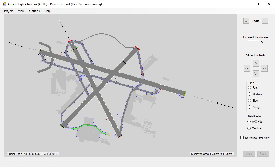
When you create an AFLT project, you specify the path to a .xml or .bgl file containing the airport of interest. AFLT then draws a faithful representation of its runways, taxiways and aprons. When your mouse hovers over a runway or taxiway, that surface turns orange. Click on a surface to select it (turns red). Now right-click anywhere on the drawing surface and you are presented with a context menu showing the lighting arrangements applicable to the selected surface. A dialog box showing the "normal" characteristics for each lighting arrangement is associated with each menu item. Each characteristic may be customized. If you have already specified an arrangement for the selected surface, the dialog instead will show the previously selected characteristics. When you are finished, representative symbols colored as specified appears on the drawing surface. Depending on the surface, individual lights having a similar function, e.g. runway centerline, taxiway left edge, approach light strobes, will be collected into groups with the members of each group connected by a line. Thereafter, these lights may be edited individually, as a line (i.e., all connected lights collectively), or as a surface component as noted above. Lighting arrangements not otherwise available in Flightsim may be created.
To save time, AFLT will import specified elements from, or all of, the stock lighting from the referenced airport definition file (which you may then customize). Note, however, runway and taxiway edge lights may not appear exactly where Flightsim places them. That's because AFLT places runway lights using FAA and ICAO standards (i.e., the "normal" characteristics used in the dialog boxes) and taxiway lights from intersection to intersection with special treatment for curves. Otherwise, AFLT uses the characteristics specified in the airport definition file.
AFLT Version 4 will also import lighting data from projects implemented with earlier versions of AFLT. Shown above is the imported AFLT3 lighting for the author's CYYJ.
In addition to specifying lighting arrangements to be applied to airport surfaces, you may place a single light or a line of lights (particularly useful for apron-edge lighting) anywhere on the drawing surface by right-clicking with no surface selected. Lines start at the right-click position and the end or "corners" are placed with a "hot cursor" following specification of the lights. When the line is completed (by a double- or right-click), any intermediate lights required by the specified spacing of lights within the line are placed automatically. You may also insert a light into a line - creating a "corner" if the line is not associated with an runway or taxiway.
As for surface arrangements, you may edit the (common) characteristics of the lights in a line or the individual characteristics of the light(s) themselves. Individual lights or whole lines of lights may be moved by selecting them and "dragging" them with the mouse. The lights at the ends of a line or "corners" within a line of lights may be dragged in any direction, the intermediate lights being automatically moved into a straight line between the ends and corners. Lights in other types of lines, e.g., edge or centerline lights, may only be moved in the direction of the line.
For clarity, the display of closed or very-narrow taxiways and/or taxi-paths may be suppressed. This is why certain taxiways near the main terminal apron are missing from the above images, such links being used in my CYYJ to accomplish drive-through parking for certain parking spots. As well, you may choose to display the lights on a dark background and to display only those lights that are subject to PCL.
Depending on the version of Flightsim with which the lights are to be used, you may specify the light source as any one of:
- brightly-textured, LOD-variable-sized 3-plane objects
- inverse-mipmapped effects
- standard effects
- BGL_LIGHTs
With inverse-mipmapped effects or the 3-plane objects, the size of the light source increases with distance, thus providing visible ranges far greater than would otherwise be possible.
When you're done, if the reference airport file contains any stock lighting of the type specified, at your direction AFLT will "strip" those stock lights from the reference airport file. You may then replace the airport definition file in your Flightsim "\scenery" folder with the "stripped" .bgl, or load the "stripped" .xml file into your airport editor and regenerate your airport.
Download this application...
ADE Ground Polys (ADE_GP) V.2.2.24.4
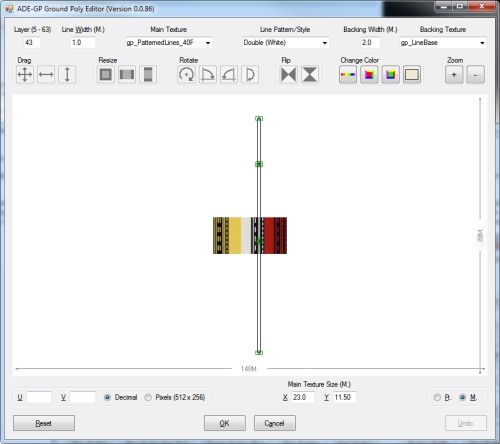
Used in association with Jon Masterson's Airport Development Editor ("ADE"), ADE Ground Polys ("ADE_GP") allows you to create ground cover and markings directly from the ADE display for use with FS9 and FSX.
By way of background, FlightSim (both FS9 and FSX) displays objects by determining for each pixel on your screen the distance from your "eye" to the point on each object in view that pixel represents. Hence, the closest object is displayed fully while only those portions of objects further away that are not covered by closer objects are seen.
But, if, for example, you have created a building and a sign mounted on it as separate objects (so as to get higher resolution for the sign), both objects will be the same distance from "your eye" and this results in Z-fighting (i.e. "flickering"). To resolve such a situation, you move the sign a short distance (a few inches/cm.) away from the side of the building.
A similar situation exists when you attempt to cover the ground with, for example, a plane (not an airplane, a flat polygon) to be textured as asphalt as the base for a parking lot. If the parking lot is away from where the user aircraft might venture, you can place that plane slightly above the ground to eliminate flicker. The further away the plane can been seen, the higher it must be elevated because, when viewed at shallow angles, the benefits of its elevation are reduced (think trigonometry). But, if that plane is right beside an apron, its elevation, unless very small, will be apparent when viewed from the user aircraft on that apron.
As well, you cannot "draw" (place planes) directly on top of runways, taxiways or aprons; you must elevate them. Elevating only a mm/fraction of an inch works fine up close, but you'll get flicker when viewed from a distance. If you elevate enough to eliminate flicker, that elevation will be readily apparent up close.
FS8/FS2002 provided a mechanism to place planes directly on the ground ("ground-polys" for short) without causing flickering, As well, planes could be placed directly on top of runways, taxiways and aprons. Fortunately, while neither FS9 nor FSX have a similar "native" capability, they will display FS8 ground-polys. Unfortunately, creating ground-polys with Gmax was a tedious and time-consuming process. But, with ADE_GP, it's a "breeze".
Download this application...
Terrain Sculptor Pro (TS Pro) V.2.1.7.4
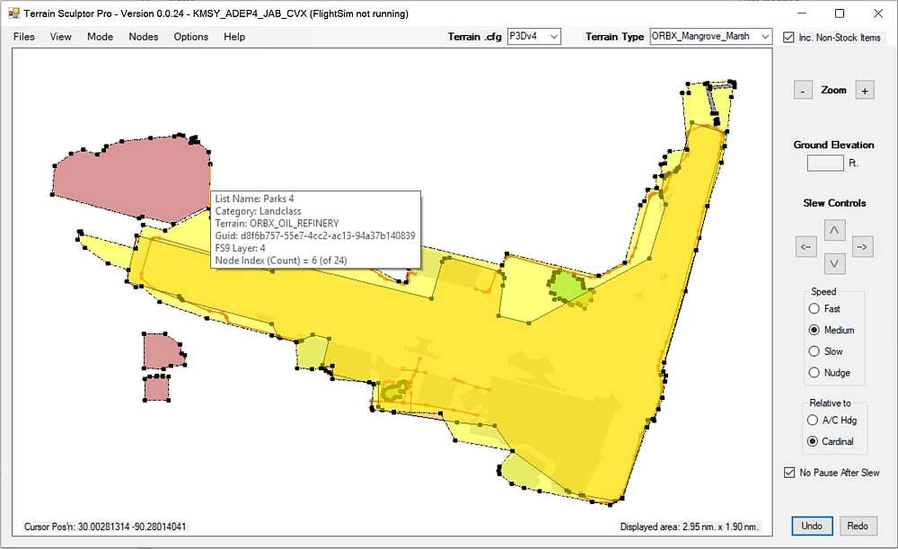
Terrain Sculptor Pro (TS Pro) is a utility to assist you in creating undulations in and otherwise making your Microsoft Flight Simulator and Lockheed Martin Prepar3D (collectively "FlightSim") terrain near your airport (or anywhere else) more representative of the real world. While other more-general-purpose tools, such as sBuilder and sBuilderX also do some of this, TS Pro's user interface is tailored for these specific functions and much of the "grunt-work" required by those other tools is done for you. Instead of requiring you to draw every sloped poly individually, TS Pro allows you to place a single node where the polys will intersect and to specify the elevation of this point. And, instead of hand-crafting individual blending triangles to mate with the existing mesh, Terrain Sculptor slews the user aircraft along a boundary you specify (with a few points), recording the mesh elevation and automatically creating these blend triangles for you.
But, that's not all. Terrain Sculptor Pro reads TDF, LWM and CVX terrain .bgls as well as .sbx files generated by sBuilder and sBuilder. Of course, you can also start terrain projects from scratch either by specifying a lat/lon position or identifying an airport .bgl. In the latter case, the project opens with an image of the airport in the background. TS Pro allows you to define and manipulate any valid FS9, FSX or P3D terrain element and compiles any set of terrain element for either FS9 or FSX, substituting equivalent terrrain elements as necessary.
All Terrain Sculptor Pro's functions are initiated from and the display is controlled from the Main Panel.
The default colours used by TS Pro are those defined in the FSX/P3D Terrain.cfg file. You can change those colors to suit your own needs, either temporarily or permanently. You can also change the color of individual elements. The display of various classes of data, e.g., streams, roads, flattens, etc? may be suppressed. Optional tooltips are available for every element. The texture assigned to each terrain element is displayed upon selection. Terrain element positions may be specified either by user aircraft position (TS Pro communicates with Flightsim via either FSUIPC or SimConnect, as available) or cursor position. For the latter, FS Pro uses a "hot cursor", i.e., once you've specified the starting position for an element, additional nodes are specified simply by repositioning and left-clicking. TS Pro allows you to load a background image as reference. For example, when adding or moving roads, it is often helpful to have stock roads as reference. You may copy elements from the background to the foreground (i.e., your data) and exclude existing data by placing the cursor over an element in the background and right-clicking. In addition to a background of terrain elements, if you are working near an airport, you can also display an image of that airport.
For a fuller description of Terrain Sculptor Pro's capabilities, please download the user manual from the menu to the left.
Download this application...
GeoLock V.1.1.0.0

When compiling a scenery .bgl file for Microsoft Flight Simulator or Prepar3D, the compiler examines each entry that positions an object and places some code in the file header that defines the geographic coverage of the placement items. In this way, Flightsim needs only examine the file header to determine whether there is anything in the file relevant to the current position of the user aircraft. This, in turn, reduces processing overhead because unneeded (relative to the user aircraft position) objects and positioning data is not loaded. The file is considered geo-locked to its coverage area.
But, there’s also a “downside” to this scheme. If the file contains any objects that might be useful outside the area to which it is geolocked, those objects are not accessible. Further, library object .bgls (which contain only object model data but no positioning data) are not geo-locked by the compiler. Hence, objects in such files are always loaded, whether or not they are needed. To address this latter situation, Microsoft geo-locked some of the stock libraries (e.g., Scenery\Orlando.bgl) when developing Flight Simulator. But, this capability is not supported by the released compilers.
Geolock to the rescue! GeoLock is a utility which allows you to
- unlock geo-locked .bgl files
- create geo-locked or unlocked subsets of models contained in scenery and object library .bgl files irrespective of whether the source bgl was geo-locked or not
In addition, GeoLock can display a 3D image of each model in a file. So, it is also useful in examining the models contains in an scenery object library.
If the file loaded into GeoLock is geo-locked, the coverage area will be shown in the Latitude and Longitude text boxes in the selected format. For other than FS8 files, if the .bgl contains any model definitions, those models will be listed in the list box on the right hand side of the dialog and the version of the models is shown in the radio-buttons above the list box. Since FS9 models don't contain any name information, the models list box will show the assigned Guid. For FSX and P3D models, the names of the models will be shown. If you hover the mouse over any item in the list box for more than 1 second, a 3D image of the model will be displayed.
If the file loaded into GeoLock is geo-locked, the coverage area will be shown in the Latitude and Longitude text boxes in the selected format. For other than FS8 files, if the .bgl contains any model definitions, those models will be listed in the list box on the right hand side of the dialog and the version of the models is shown in the radio-buttons above the list box. Since FS9 models don't contain any name information, the models list box will show the assigned Guid. For FSX and P3D models, the names of the models will be shown. If you hover the mouse over any item in the list box for more than 1 second, a 3D image of the model will be displayed.
If the file is not geo-locked (i.e., the Latitude and Longitude textboxes are all blank), it may be locked by specifying the bounding latitudes and longitudes and "pressing" the Geo-Lock button.
To create a locked or unlocked subset of the models, first select the models of interest. If you wish the subset to be geo-locked, specify the bounding latitudes and longitudes of the area in which those models are to be active. Then, "press" Geo-lock or Unlock as applicable.
Download this application...
This page was last modified on Sunday, 10 September 2023 - 23:58